Wooden Stick Bridge
Advanced Solid Mechanics Project
Oct 2022 - Dec 2022
Objective
Design and build a bridge made out of off-the-shelf wooden sticks and adhesives. The bridges were to be built within strict dimensions (image can be seen in Methodology). The bridges were given marks for its max load, max energy, and bridge weight. Bridges were graded in comparision to the best performing bridge.
Methodology
Multiple tests utilizing the UTM for tensile, compression, and bending tests were conducted. These were needed to find properties of the wooden sticks and to ensure the different orientations and lamination techniques were of the highest strength.
Above is the restriction box for the bridge outlining the dimensions and possible locations for the bridge. Our group chose to use Topology Optimization to increase our performance to weight ratio. Thus, starting from maximum size within this boundary box is the most logical approach.
The software chosen to perform this Topology Optimization was SolidWorks. This was due to limited time for the design phase, avaliability of the software, and ease of use. It was understood that SolidWorks could not optimize for the maximum strength (chose stiffness instead) and does not provide the highest FEA accuracy. Our group decided that these shortcomings did not outweigh the benefits.
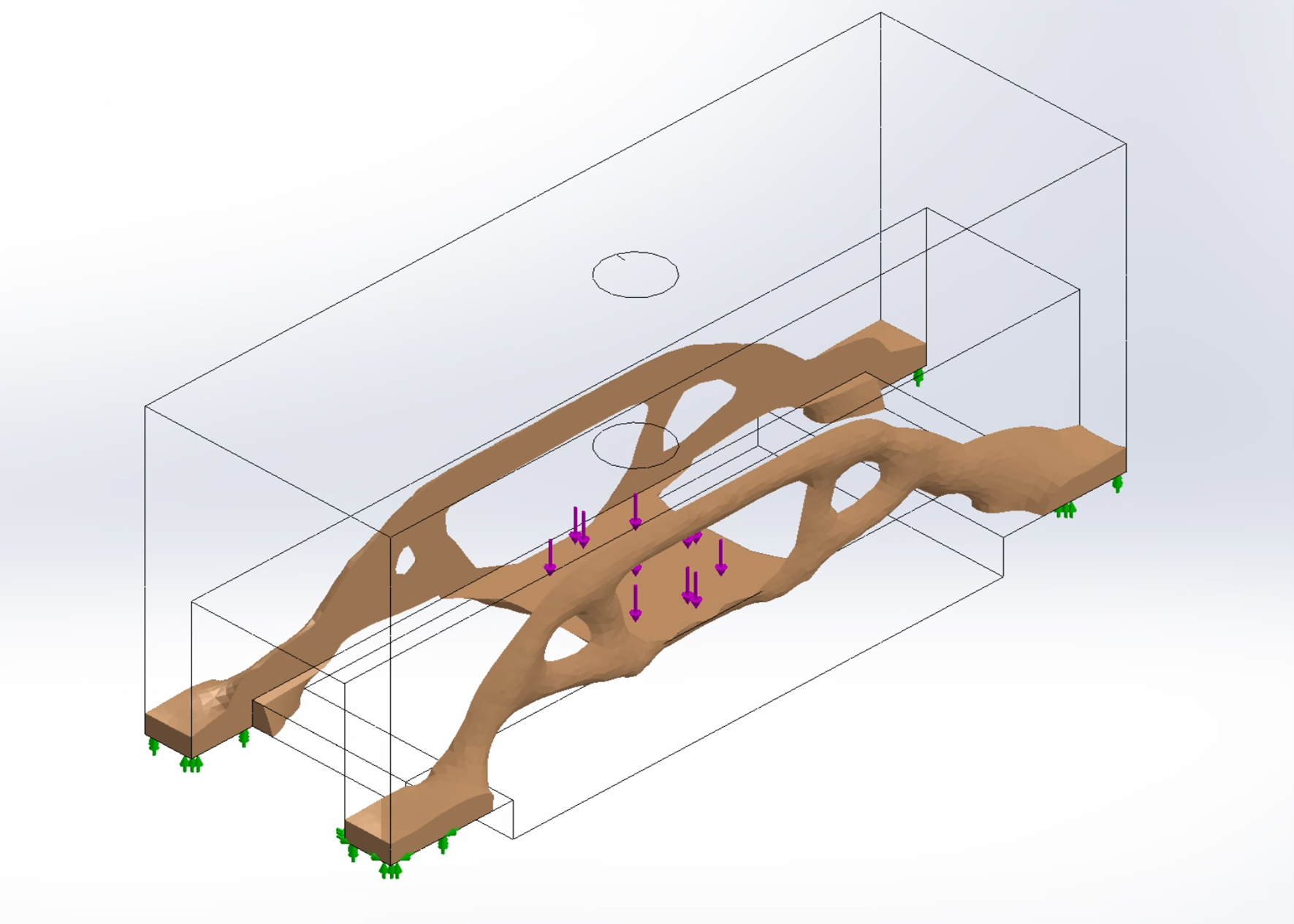
After numerous simulations, varying cell sizes and boundary conditions, the geometry above was the final bridge geometry. It is important to note that all bridges in the real world need to carry significant load across the span of the bridge. Due to the testing/grading methodology of this project (where all the load is applied only to the middle) the bridge is optimized to only need structural members to support the middle. Thin non-structural pieces were to cover the entire span of the bridge (rules indicate that the bridge cannot have gaps and must allow a small scale car to be driven across).
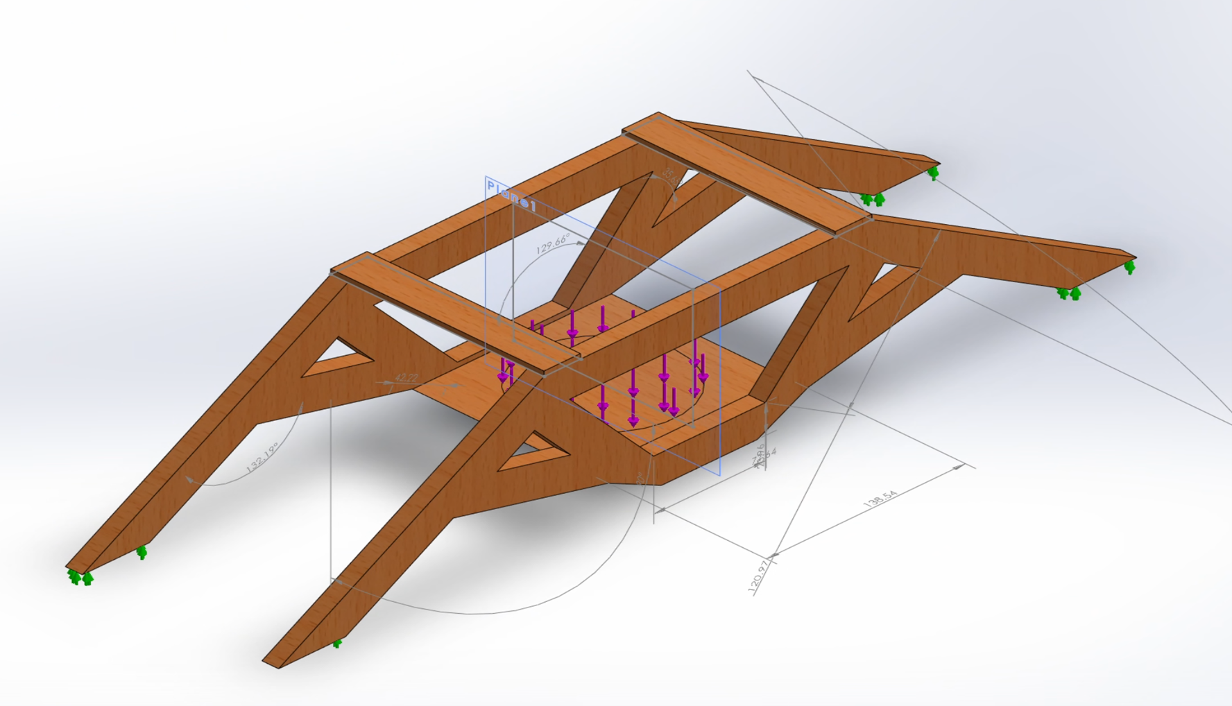
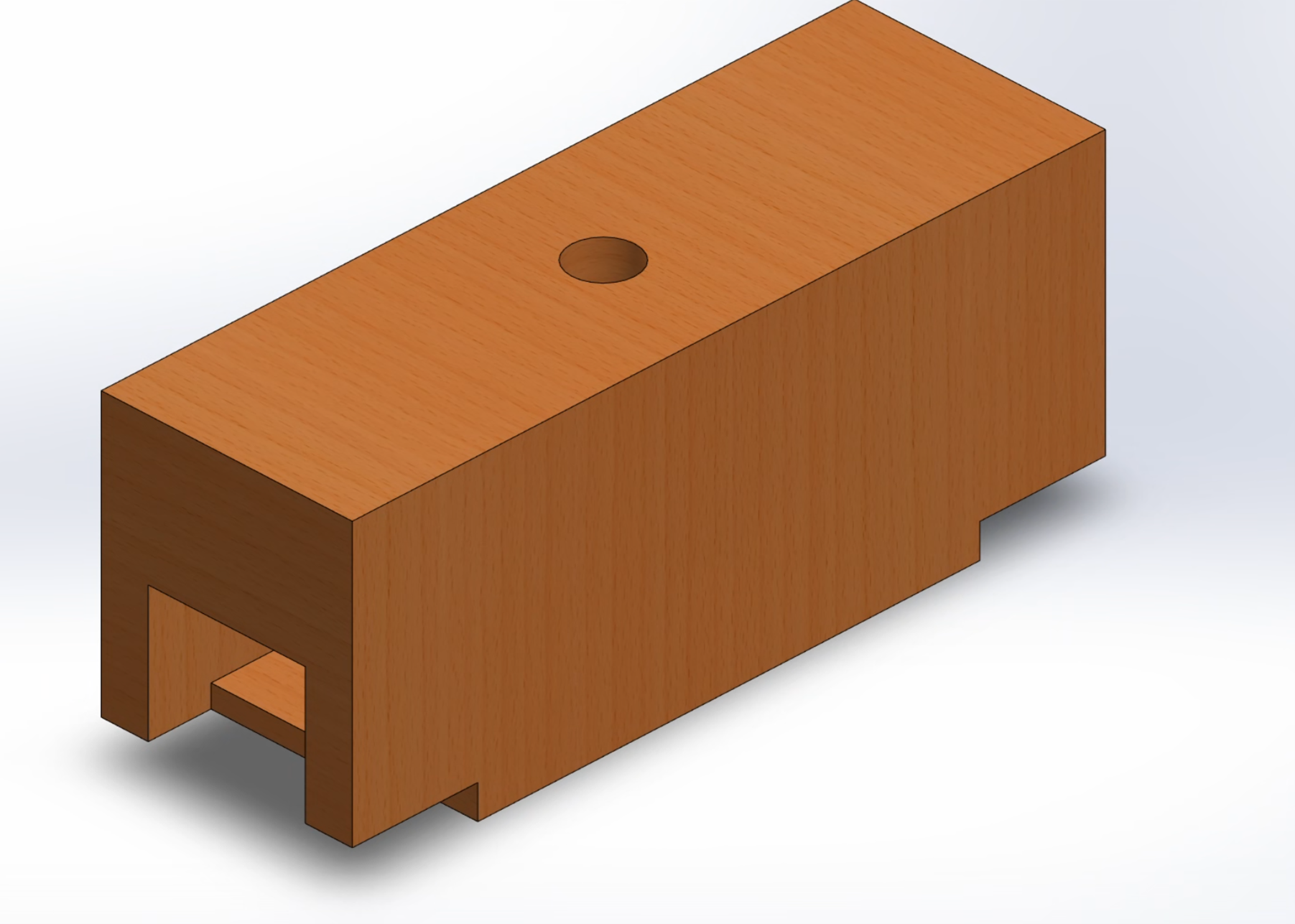
In its raw optimized form, the bridge could not be easily manufactured and need to be remodeled to be manufacturable.
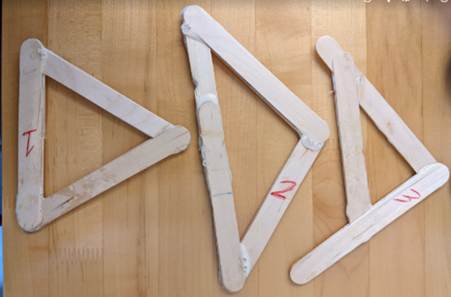
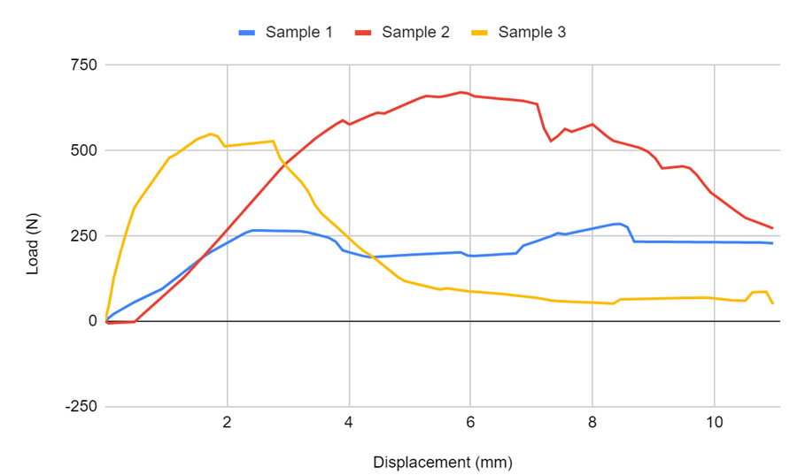
At this point the bridge geometries needed to be validated. Multiple bending tests were conducted on small frame designs. It was found that Sample 3 had the most stiffness out of the three designs. It was also assumed that Sample 3's max load should be close to Sample 2 if it had the same number of sticks and width. With that, confidence was high and manufacturing the bridge was underway.
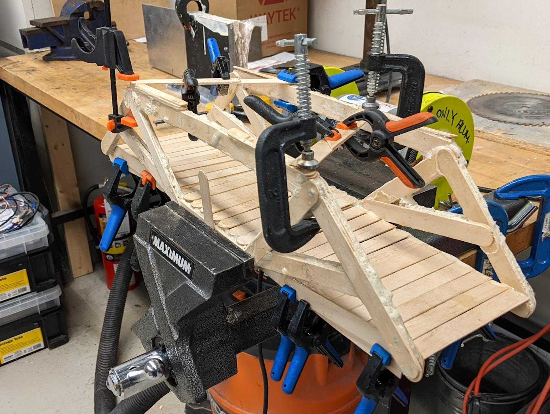
Nearing the end of the project, it was found that there were not enough sticks to complete the solid floor that was initially designed. Instead only three beams were placed under the floors.
Results
The bridge was placed on a UTM and loaded until the machine reached an extension of 30 mm where the bridge will be considered "failed".
Max Load: 2246.5 N/230 kg, Max Energy: 30.53 kJ, Weight: 0.435 kg. Overall Top Three best performing bridge out of 30 groups.
As shown in the video, the bridge gave way around the floor. Looking back, we should have glued in a lip that overlapped and provided additional support under the bridge.
Our Team